I. Interactive Mode.
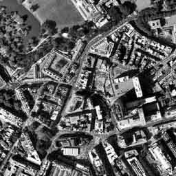

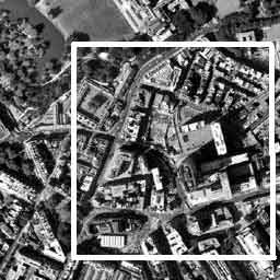
a). It is allocated with the operator with the help of the mouse.
b). The full image (without participation of the operator).

Source Data:1. Width of cell CCD = 14 [mKm]. 2. Heigth of cell CCD = 12 [mKm]. 3. Bit capacity of the Analog-Digital Conversion = 11 bit. 4. Diameter of a mirror = 350 [mm]. 5. Focal distance= 4750 [mm]. 6. Photographic altitude = 569000 [m]. 7. Angle of Sun= 30 [degree]. 8. Viewing angle = 25 [degree]. 9. Compensation Factor Cp = 1.0. 10. etc. |
Source Data Input a). The operator enters data manually and keeps parameters in a file. b). Parameters are loaded from a file automatically. |

Measurement of OES resolution |
It is performance automatically, without participation of the operator. |

Output of calculation results :1. Name of the image file. 2. Modulation Transfer Function = data curve. 3. Noise Level [quantum]. 4. Resolution of focal plane V [1/ mm]. 5. Ground Resolution (spatial resolution) L [m]. 6. etc. |
It is automatically, without participation of the operator.
|

Data Base |
Preservation in a DataBase (under the instruction of the operator). |

Database Output to the monitor |
Under the instruction of the operator.
|
II. Physical Principles.
a). Concept of detection probability for discrete system.
| CCD discrete structure: | Object: | Decision making: |
 |
 |
Detection Level |
 |
 |
Recognition Level (automobile) |
 |
 |
Type Level ("Ford") |
 It is probability P |
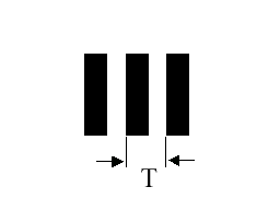
b). Our detection model (object = optical test charts).
| Object "O" | OES channel | Signal "S" |
 |
MTF transfer function
Noise N |
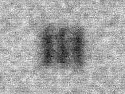 |
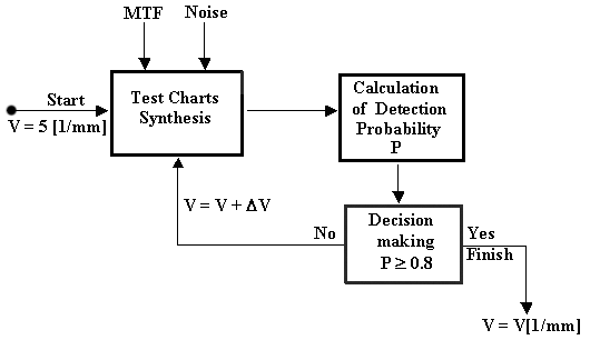
V = T/2 [1/mm] - spatial frequency.
The Detection Probability is proportional to a signal-to-noise ratio: P ~ <O – S>/N,
where <> mean operator.
Sequence of detection stages:
c). Design formula of Spatial Resolution L.
where
V - Resolution of focal plane (CCD plane) ,
f - focal distance of telescope,
u - viewing angle,
D - slant distance:
D = [h² + 2×R×h + R²×cos²(u)]½ – R×cos(u),
R - radius of the Earth,
h - photographic altitude.
III. Measurement of the MTF and OES noise.
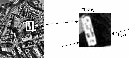
During the analysis of the image, the PP in an automatic mode recognition the of knife-edges image B(x,y). The border between light and dark objects refers to as knife-edge. Distribution of intensity U (x) in a direction perpendicular knife-edge refers to as a boundary curve.
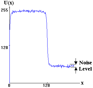
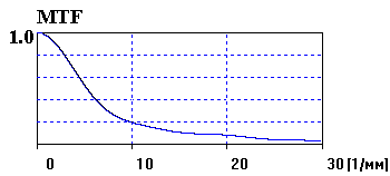
Transfer function OES is calculated as Fourier transformation from a derivative boundary curve dU(x)/dx:
MTF - Modulation Transfer Function,
v - spatial frequency [1/mm],
F - Fourier transformation operator.
The example of Modulation Transfer Function is shown below:
Simultaneously with calculation MTF, the PP measures noise level N.
IV. Visual expert estimation.
The visual expert estimation will be carried out at an initial stage of space photography and serves for correction of detection model:
where Cp - Compensation Factor, which is determined during an expert estimation.
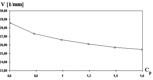
Stage 1. At the first stage the typical fragment with the help of the PP is measured. Variable parameter during measurements is the Compensation Factor, which is set by the operator in the initial data table in limits from 0.2 up to 2.0 with step 0.1 (or 0.2). As a result of measurements to be under construction functional dependence of resolution V [1/mm] from Compensation Factor Cp. The example of such dependence is shown on the diagram below.
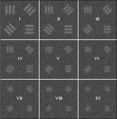
Further, the visual expert estimation is carried out at an orbit change, in case of CCD change or replacement of a telescope.
 Print
Print